This model adapter will work for Quicksilver G4s. This adapter is the most difficult to make as these systems have non-ATX-compliant power requirements and wiring schemes, plus require a second power adapter for the CPU.
Before getting started, I would like to go over the potential drawbacks to using an ATX power supply in these systems.
ADC Power will be disabled. ADC Power is used to provide power to several Apple Cinema Displays. Since the adapted power supply will not be able to provide the 28v required for these displays, you won't be able to use them any longer.
Deep Sleep may not be reliable. Macs require a minimum of 5v during deep sleep, which is deliverable from an ATX power supply. Unfortunately, ATX power supply build quality varies greatly and not all power supplies are capable of supplying this power reliably when the machine switches into or out of deep sleep. If your power supply isn't capable of delivering reliable power, your system may not sleep, or it may experience freezes when waking up. In these cases, it is advised you consider a different power supply or preventing your system from going to sleep.
Using a Firewire Device while having an Apple ROM Maxtor Hard Drive installed in your tower may result in that drive ceasing to function. Details are sketchy on this, my own testing hasn't experienced any problems, but please be aware that this is a potential problem.

The beginning of the modification is pretty straightforward.
I use ATX 20-pin to 24-pin adapter cables to begin my modification to make things easier and to keep the power supply unmodified.
You will want to remove the -5v, Power OK, +5v Trickle, +12v, and one of the +3.3v lines (a split connection, if possible), and set them aside. Next, remove any remaining wires that won't be needed. At this point, you can rearrange wires that are different from ATX to Quicksilver.
You may have an empty ground line or two, this is ok. Just make sure that any missing connection is near a similar line.
You'll need to connect the +3.3v line to the Power OK line and insert these back into the harness.
The next part of the conversion is by far the most difficult.
Start by cutting the trickle line about 2" from the male connector. Now strip off 3/4" of insulation from each end and tin the wires with solder. For the +12v line, it's easiest if you try to avoid cutting the wire. You'll want to remove the insulation so that the bare wire matches up with the male trickle wire. I carefully strip the insulation off the 12v line using a razor knife. You will also need a spare wire to splice onto the +12v line to use for the second +25v connection on the QS.
When using 20 to 24 pin adapters, the included 12v line is often very low gauge. If you have a spare wire that is thicker, you should substitute it in for the 12v line. Since G4s don't require -5v connections, I use that wire for 12v.
 |
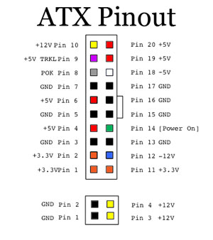
Now it's time to add the diodes. I use 3-Amp diodes with a 50v PIV rating from All Electronics These diodes have proven to be powerful enough for all of the uses so far. PIV stands for Power Inverse Voltage, the amount of power the diodes are capable of preventing from flowing in reverse, this is important because we need the diodes to isolate the lines from flowing back into the power supply. The diagram on the left shows how the diodes are to be wired for the adapter. This system allows the G4 to receive +5v trickle power while the system is off and +12v power while on, but preventing the +5v from leaking into the +12v while off and preventing the +12v from leaking into the +5v trickle in the power supply while on. This results in the G4 getting +5v power when off, just enough to start the system and preserve the memory when in deep sleep. When on, the system received +12v which is used to power Firewire devices. The +12v available to firewire devices is near the lower end of the firewire specification and may not work with every device. The second +12v line is needed by some video cards which use the ADC power connection for additional power. +12v is NOT enough to allow usage of an ADC powered monitor. |
Once you have the diodes soldered and the connections covered, you can plug the wires back into the ATX adapter. At this point, you should double-check all the connections, wiring sequences, and make sure all splices and solder joints are well covered to prevent shorts.
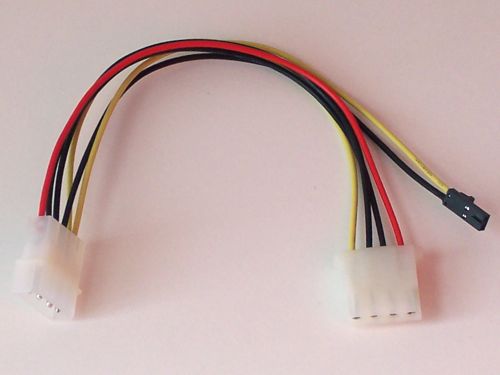
This is how my Quicksilver adapter looks:

The last part of the Quicksilver adaptation is the CPU power connection. In the PC world, this is referred to as the P4 connector. It's a 4 pin connector with two +12v wires and two grounds. Of course, Apple couldn't use standard wiring, so they reversed the polarity of this connection. You can buy adapter cables which will convert a spare hard drive molex connector to a P4 connector, or you can use the connector on your power supply if it's long enough, but you will need to reverse the polarity before you use it. I include a CPU power cable with every Quicksilver ATXG4 kit.
For convenience, I also include power adapters to use to connect the Apple case fan to the new ATX power supply. This adapter plugs into a normal hard drive power connector and provides a connection to the fan. The adapter has the ends crimped into the molex connector to give a clean look with no unsightly splices.